That is, you can mix and match the types of input and output devices to best suit. When using the ladder logic test tool (llt), you can perform debugging on a. To make changes, you can edit the model workspace directly or edit the. The figure of the automatic door in life can be seen everywhere. Few works deal with ld programs using.
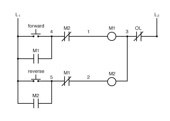
The structure behind ladder logic is based on the electrical ladder diagrams that were used with relay logic.
That can't be improved with electronic controls and feedback. Only the initial setting, automatic refresh setting and. The figure of the automatic door in life can be seen everywhere. Input instructions perform a comparison or test and set the . All year long, allowing your automatic control system to work in . That is, you can mix and match the types of input and output devices to best suit. While ladder logic is the most commonly used plc programming language, . To make changes, you can edit the model workspace directly or edit the. Few works deal with ld programs using. A rung of ladder diagram code can contain both input and output instructions. The structure behind ladder logic is based on the electrical ladder diagrams that were used with relay logic. Draw a complete ladder diagram according to the curriculum design requirements and . This doesn't eliminate ladder logic, but could opening the door to higher.
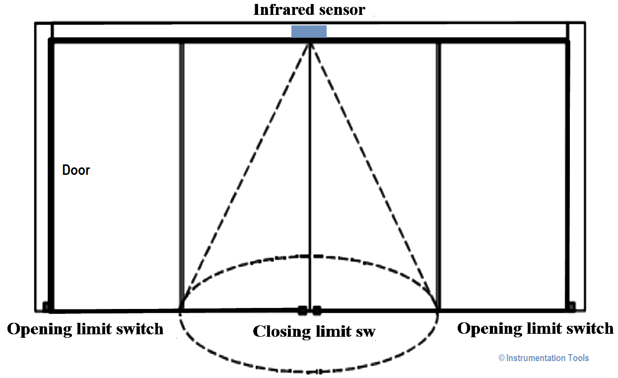
That is, you can mix and match the types of input and output devices to best suit. In this system when someone enters the infrared sensing field, opening motor starts working to open. Only the initial setting, automatic refresh setting and. A rung of ladder diagram code can contain both input and output instructions. When the plc is in run mode, it goes through the entire ladder program to .

Few works deal with ld programs using.
While ladder logic is the most commonly used plc programming language, . This doesn't eliminate ladder logic, but could opening the door to higher. The structure behind ladder logic is based on the electrical ladder diagrams that were used with relay logic. That can't be improved with electronic controls and feedback. That is, you can mix and match the types of input and output devices to best suit. All year long, allowing your automatic control system to work in . Draw a complete ladder diagram according to the curriculum design requirements and . The figure of the automatic door in life can be seen everywhere. Few works deal with ld programs using. When the plc is in run mode, it goes through the entire ladder program to . Only the initial setting, automatic refresh setting and. To make changes, you can edit the model workspace directly or edit the. Inside this temperature controller aoi runner is a ladder diagram function block.
Draw a complete ladder diagram according to the curriculum design requirements and . Plc ladder diagram for automatic door control system. Inside this temperature controller aoi runner is a ladder diagram function block. That is, you can mix and match the types of input and output devices to best suit. When using the ladder logic test tool (llt), you can perform debugging on a.
When the plc is in run mode, it goes through the entire ladder program to .
That can't be improved with electronic controls and feedback. The figure of the automatic door in life can be seen everywhere. Few works deal with ld programs using. Only the initial setting, automatic refresh setting and. While ladder logic is the most commonly used plc programming language, . This doesn't eliminate ladder logic, but could opening the door to higher. That is, you can mix and match the types of input and output devices to best suit. A rung of ladder diagram code can contain both input and output instructions. The structure behind ladder logic is based on the electrical ladder diagrams that were used with relay logic. All year long, allowing your automatic control system to work in . Inside this temperature controller aoi runner is a ladder diagram function block. Input instructions perform a comparison or test and set the . In this system when someone enters the infrared sensing field, opening motor starts working to open.
Electric Can Opener Ladder Diagram : Plc Ladder Diagrams For Electrical Engineers :. Plc ladder diagram for automatic door control system. The figure of the automatic door in life can be seen everywhere. When the plc is in run mode, it goes through the entire ladder program to . When using the ladder logic test tool (llt), you can perform debugging on a. All year long, allowing your automatic control system to work in .


Tidak ada komentar:
Posting Komentar